The ComplexClock is a free-running master clock and a switchable divider. 6HP by 3U by about 20mm deep. Dual tempo knobs give you coarse and fine control. Master on-off switch is a vital feature.
The jack at the top is an input so you can be sync’ed to another master clock and use the divider. If you want voltage control over the tempo, you’d input that here from an LFO or a VCO. There’s a discrete Schmitt Trigger so you can use a soft triangle and it becomes a hard square, to better serve the dividers.
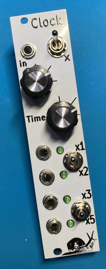
The internals are analog, so the divider will run at audio rate if you want to use them as a sub-oscillator.
The four outputs are progressively slower divisions: first is a halving, then the last two are controlled by the switches to be thirds or fifths, and half that. With both switches up, you get the fastest divisions: 1x,2x,3x,6x. With both switches down, you get the slowest divisions: 1x,2x,10x,20x.
Power draw is 11mA on the +12V and 0 mA on the -12V. The LEDs are the major draw so it will flicker in time. The clock outputs about 11 volts, with a 1k output resistor so it can draw another 11 mA if you short the output to ground, (all four means worst case possible is 55 mA of 12V used if you short everything to ground).
| Price | Notes | ||
| PCB+Panel | $30 | ||
| Full Kit (incl PCBs) | $72 | ||
| Built and Tested | $122 |
Guide and BOM for v111 and 112
Guide and BOM for v122 and an ibom
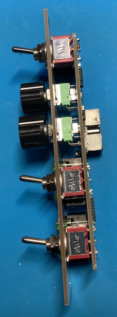
Depth is 20mm due to one PCB and SMT, then a shrouded header. Your power cable will add 5mm behind that.

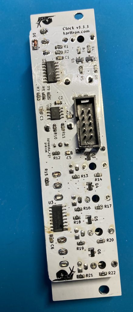
NOTE: SMT0805 construction means you need good eyesight and tweezers to build this kit. It’s doable by hand if you have some soldering experience already. The chips are SOIC with a 1.27mm pitch so you will need the soldering accoutrements: copper braid and/or fluid flux to keep the pins apart before powering the circuit. These tools are not included with the kit.
Building Tips
The switches are not the same height as the jacks, so your PCB may be crooked if you don’t set the washers just right. It doesn’t hurt anything to have a crooked PCB, but you may want to try a few settings while building to get everything as level as possible.
Check that the transistors are face-up. You should be able to see some text on the top.
If you built it and find the bottom two outputs are not activating, check that the IC pins are properly soldered down.
Modifications
The capacitor at C3 sets the timing by filling and emptying, so a larger value will give you a slower clock, and a smaller value will give you a faster clock. I have it at 10uF but you can try anything.
When the speed knobs are up to maximum and you get audio-rate clocking, the timer chip is filling and emptying a capacitor at maximum speed. This is the most power used, and some SMD/MLC capacitors will “sing”. Cheap caps can make noise and it’s nothing to worry about, bring the clock speed back a little so you can’t hear it.