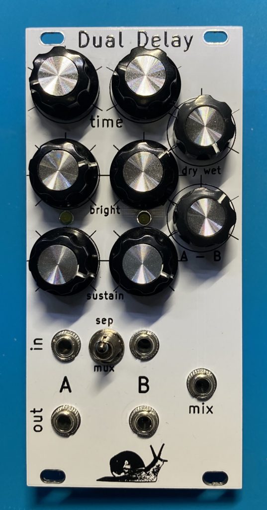
The Dual Delay is a 12HP effects unit for Eurorack. Analog controls mean it always sounds unique. Digital backing makes it reliable and compact. The circuit uses two PT2399, two opamp crossfaders and SMT 0805 construction.
At high values of the feedback knobs it goes into a chaotic self-oscillation, trimmed by the LEDs, so your LED choice will impact that character.
This circuit, like every circuit, is a modification of stuff I learned from others online and also here.
Specs:
Two independent digital delay units, a switch to mix the inputs together, and a dual crossfader circuit letting you pan between dry/wet and the A/B circuits.
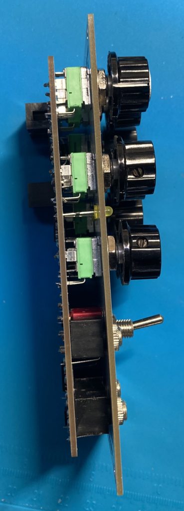
Just 24mm deep, 12HP wide.
Delay Time Range. Analog controls have some variance, so at a minimum I’ve measured between 35 and 40 milliseconds when the time knob is full counter-clockwise. At ‘noon’ I’ve measured 430 to 450 milliseconds delay, at ‘3-oclock’ it’s about 900ms, and at full clockwise it’s 1100 to 1250 milliseconds.
The delay core is a PT2399, which has well known noise characteristics: the internal memory is used differently for a short delay and a long one, to fit a longer section in the audio quality degrades, so there’s noise on your echos at very long delay times. I think this is normal for any hardware delay, and it’s a tradeoff. This module gets audibly noisy after about the ‘1-oclock’ region, about 620ms.
Power draw is 20 mA on the -12V, and either 50 or 80 mA on the +12V depending on the style of 5V source you use. The linear 7805 is cheap and quiet, but gets warm, and 80 mA might be too much for your tastes, so my kits include a 7805 drop-in switcher by Recom so the whole unit comes down to 50 mA on the +12V rail.
Build Guide and BOM , updated v2.2.4. Works with board v2.2.1, simpler than the previous listing. Fewer kinds of capacitors, same performance.
Build Guide and BOM and an ibom html. For board v 2.2.1
| Kit Type | Price | Note | |
| PCB/Panel set | $30 | ||
| Full Parts Kit (incl PCB) | $115 | ||
| Built and Tested | $165 |
NOTE: SMT0805 construction means you need good eyesight and tweezers to build this kit. It’s doable by hand if you have some soldering experience already. The chips are SOIC with a 1.27mm pitch so you will need the soldering accoutrements: copper braid and/or fluid flux to keep the pins apart before powering the circuit. These tools are not included with the kit.
Guide for setting the LED resistors:
R13 and R14 are the LED resistors. The LEDs indicate audio level in each delay, but are designed to clip the feedback. The color and brightness will change the tone the runaway feedback. Technically the audio signal is stored in a 0-5V digital memory and the LED is allowing some of the signal to fall away. Both the forward voltage and the limiting resistor will control how much of the signal is used. For example, omitting the LED will keep 100% of the signal and cause the harshest chaos noise when the feedback knobs are up all the way. At the other extreme, an overdriven low voltage LED will prevent the module from significant self-oscillation. My BOM has chosen an amber LED and a 10K to put the tone in between those two extremes, with a muddy self-oscillation possible.
Construction Troubleshooting
Known issues, I have had an opamp on upside down, which causes a short. Be sure the pin1 is towards the top, for all chips. The big diodes have a line marking their direction. I have also sometimes missed soldering one side of a resistor, it’s hard to see, so check you have all connections made.
Standard troubleshooting, trace where the power goes. Does it come in the socket? Power should cross the big diodes, unless they’re in backwards. Then you’ll have +/- 11.5V over at the opamps. (that’s 12 minus the diode drop) If they’re in backwards they will short and draw down the power line, while getting hot. It’s easy to have a TL074 on backwards. If the TL074 and TL072 are on the right way and have +/- 11.5V, then they should be working and see if you get 5V at pin 1 of the PT2399s. Pin 2 should be 2.5V and pin 3/4 should be 0V. I have also sometimes missed soldering one side of a resistor.
If the PT2399 are in right they should go to self-oscillation with both feedback knobs and mix knobs up all the way (clockwise), and you’ll see the LEDs start lighting, even with no signal coming in. If you have the LEDs lit and no signal coming out, then they’re generating sound and the issue is on the output TL072, where you should be able to find signal A at pin 1 and signal B at pin 7.